
The Mowery Tellurian: 3D-Printable DIY Kit
Bounty Yield
7,500 SP+ Royalties
"In October of 1899, Robert Mowery of Arkansas patented this magnificent Tellurian. It was engineered not just to spin, but to physically illustrate the ebb and flow of the tides, the changing of the seasons, and the equinoxes. Mowery designed an ingenious elliptical track and a vertical cam-actuated rod to maintain the Earth's perfect 23.5-degree axial tilt as it orbits the Sun. However, translating his 19th-century cast-iron linkages into a modern, 3D-printable DIY assembly kit is a staggering challenge. I leave it to the Vanguard to resurrect his masterpiece for the modern Maker's desk."
— The Time Traveller
Archival Addendum // Foundation Records
Mowery's genius never reached the mass production lines of the 19th century. The physical prototype was lost to private collections, and the machine remained an unfulfilled dream. The Vanguard is hereby authorized to grant this magnificent mechanism the global production run it was denied a century ago.
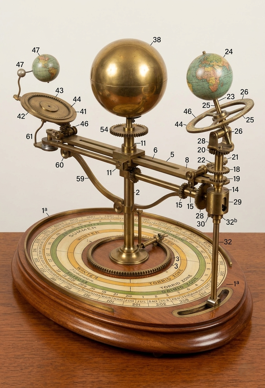
Artificers, pay close attention to the provided full-color reference model, mapped directly to the original patent digits. The entire sub-assembly is driven by a primary pinion (Part 15) traversing a circular rack (Part 3).
To achieve a functional 3D-printable model, we must solve the lunar kinetic void. Mowery's patent utilizes an annular carrier (Part 43) with internal gear teeth (Part 44) driven by a pinion (Part 46) to rotate the Moon (Part 47) around the Earth (Part 24).
Kinetic Formula: The Lunar Orbit
The Moon must complete roughly 12.37 orbits (synodic months) for every 1 full rotation of the Earth assembly around the Sun. We calculate the required gear ratio R using the internal ring gear (Nring) and the driving pinion (Npinion):
I have calculated the optimal FDM-printable tooth counts to achieve this ratio without utilizing microscopic gears:
*Note: An 8-tooth pinion requires a modified involute profile to prevent undercutting during 3D printing. Adjust your pressure angle to 25 degrees.
Your most difficult task is adapting Mowery's Cam Groove (Part 34). This groove raises and lowers the operating rod (Part 32) to tilt the Earth bracket. As you design, remember you are engineering a DIY Assembly Kit for the Mercantile.
The Foundation Standard
To claim this Bounty and achieve Canonization, your submitted files must fulfill the following modular requirements. The final product must be a true multi-material DIY Assembly Kit.
The Central Pillar (Part 5) with a housing for an 8mm brass rod. The Elliptical Track (Part 9) must be sliced into 4 interlocking dovetail segments to fit standard print beds.
The main radial frame (Part 27) featuring a snap-fit carriage for a 608ZZ bearing to glide smoothly along the elliptical track.
The 99-tooth internal annular ring gear (Part 44) and the 8-tooth drive pinion (Part 46) calculated by the Archivist.
The vertical cam-groove bracket (Part 34) and sliding rod (Part 32) that mechanically forces the Earth's 23.5° seasonal tilt.
The Sun, Earth, and Moon globes. Must be modeled as hollow spheres (1.2mm wall thickness) with a 5mm bottom aperture for LED diode insertion.
A Vanguard LifeCraft requires physical ballast. Do not mandate a 3D-printed plastic base. You must export a 1:1 scale .DXF or .PDF routing template of the base geometry. This allows our Woodworking Artificers to mill the foundation out of solid walnut, mahogany, or oak, complete with the precise drill-hole coordinates for the M3 mounting screws.
Design your STL files to accept these standardized physical components:
Have you successfully converted the Archivist's math into a multi-material CAD assembly kit? Submit your files for Canonization.
Proceed to Foundry Portal